Research On Die Casting Mould Gating System
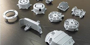
Die casting is one of the important means for non-ferrous metal forming. During the die-casting process, due to the different flow states of the molten metal in the cavity, undesirable phenomena such as cold barriers, patterns, pores, and segregation may occur. In order to prevent these undesirable phenomena, it is quite necessary to control the flow of molten metal in the cavity. The key to controlling the flow of molten metal in the cavity lies in the research and design of the die-casting die gating system.
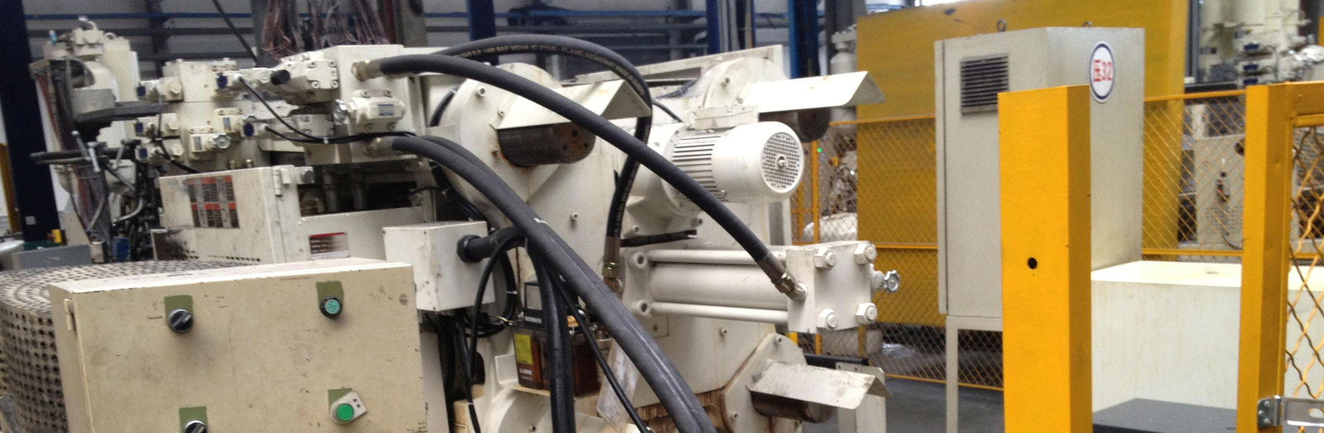
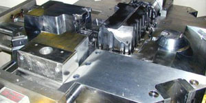
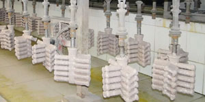
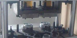
The Production Process Of Die-Casting Molds
The CAD/CAE/CAM/CAT process of die casting mold making.
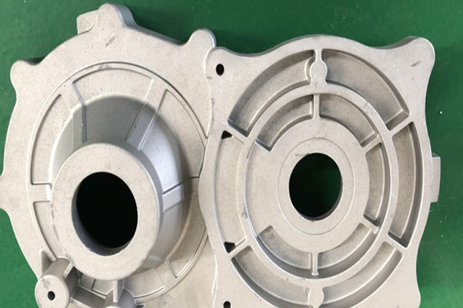
The Design Of The Die Casting Mold Pouring System
In the research of the die-casting die gating system, the gate position and shape are important factors to control the flow state and filling direction of the solution. First, focus on the location of the gate and the shape of the runner, design the gate, runner, slag bag, overflow trough, and exhaust duct; then use CAE software to analyze the flow of solution inside the cavity. The position and size of the inner runner and the inner gate have a decisive influence on the filling method.
The Design Of The Inner Gate
When setting the gate on the finished product, it is usually carried out according to the following procedure:
- Calculation formula of gate cross-sectional area: A=U/(vt): product volume (cIn.):A: Gate cross-sectional area (cm2)/v: Gate aluminum solution speed (cm/s)/T: Filling time (s)
- Calculate the cross-sectional area of the inner gate.
- According to the cross-sectional area of the inner gate, set the gate shape, and then set the gate position, and initially design the position of the flow trough and the slag bag.
- Make different gate schemes (usually make the cross-sectional area of the inner runner smaller first, and expand it when necessary after the test), and make 3D data.
- Carry out CAE analysis (that is, flow analysis) based on the produced 3D data.
- Evaluate the analysis results.
- If there are unfavorable phenomena after the evaluation, the plan should be improved, and then CAE analysis should be carried out until a more satisfactory plan is obtained.
Design Of Sprue And Exhaust System
The inner gate should be set at a position where the molten metal flows best in the cavity, the exhaust is filled, and all corners of the cavity can be filled with molten metal. Use an internal gate whenever possible. If multiple internal gates are needed, care should be taken to ensure that the flow of molten metal does not interfere with each other or meet in the cavity without dispersing (ie guiding the metal flow to flow in one direction) to avoid the convergence of the molten metal in the cavity vortex.
When the size of the die-casting is large, it is sometimes impossible to obtain the required cross-sectional area of the runner from only one runner, so multiple runners must be used. However, it should be noted that the setting of the inner runner should ensure that the molten metal is guided to flow only in one direction, so as to avoid eddy currents when the molten metal in the cavity merges.
The molten metal stream should turn as little as possible in the cavity so that the molten metal can reach the thick-walled part of the die casting.
The molten metal flow should be as short and uniform as possible.
The cross-sectional area of the inner runner is gradually reduced toward the inner runner to reduce gas entrainment, which is beneficial to improve the compactness of the die casting. The inner runner should be smoothly transitioned during the flow process to avoid sharp turning and flow impact as much as possible.
When there are multiple cavities, the cross-sectional area of the runner should be reduced in sections according to the volume ratio of each cavity.
The air in the cavity and the volatilized gas of the lubricant should be pushed to the exhaust groove by the flowing molten metal, and then escape the cavity from the exhaust groove. In particular, the flow of molten metal should not leave the gas in the blind hole and block the exhaust groove prematurely.
The metal stream should not form a thermal shock on the poor heat dissipation. For die castings with ribs, the metal should flow in the direction of the ribs as much as possible.
It should be avoided that molten metal directly washes away easily damaged mold parts and cores. When it is unavoidable, an isolation zone should be set on the sprue to avoid thermal shock.
Generally, the wider and thicker the inner runner, the greater the risk of non-uniform flow. At the same time, try not to use excessively thick gates; avoid deformation when cutting the gates.
Exhaust Of Cavity
The overflow trough is used to remove the molten metal sprayed initially during casting and to make the temperature of the mold consistent. The liquid flow groove is set at the position where the mold is easy to contain gas, and is used for exhaust gas to improve the flow state of the molten metal and guide the molten metal to all corners of the cavity to obtain a good casting surface. The exhaust groove is connected to the front of the overflow groove and the slag bag, or directly connected to the cavity.
The total cross-sectional area of the exhaust slot should be roughly equivalent to the cross-sectional area of the inner runner.
The position of the exhaust groove on the parting surface is determined according to the flow state of the molten metal in the cavity. The exhaust groove is best to be "not straight" but "curved" to prevent the molten metal from spraying and hurting people. The depth of the exhaust groove on the parting surface is usually 0.05mm-0.15mm; the depth of the exhaust groove in the cavity is usually 0.3mm~0.5mm; the depth of the exhaust groove on the edge of the mold is usually 0.1mm~0.15mm ; The width of the exhaust slot is generally 5mm~20mm.
The exhaust gap between the ejector pin and the push rod is very important for the exhaust of the cavity, usually controlled at 0.01mm-0.02mm, or enlarged until no burrs are produced.
The fixed core exhaust is also an effective exhaust method. Usually, a gap of 0.05mm-0.08mm is controlled on the periphery of the core, so that the core positioning neck is opened with an exhaust slot width and thickness of 1mm-2mm, and the gas in the cavity is opened out of the exhaust slot along the neck. It is discharged from the bottom of the cavity. The roughness of the exhaust slot should not be neglected. It should maintain a high degree of smoothness to avoid being blocked by the paint sticking to the dirt during use, which will affect the exhaust.
Flow Analysis Evaluation And Countermeasures
In the mold design process, the metal flow should be allowed to flow in one direction as much as possible. After the flow is analyzed, when eddy currents are found in the cavity, the inner gate lead angle or size should be changed to eliminate the eddy current state.
When molten metal meets, let the molten metal continue to flow for a certain distance before stopping the flow; therefore, an overflow trough and a slag bag should be added outside the cavity at the junction to allow the supercooled molten metal and air compounds to flow into the overflow trough And the slag bag; let the subsequent molten metal be clean and at room temperature.
When the filling speed of different parts is different, the thickness or width of the inner gate should be adjusted (gradually increase if necessary) to achieve the goal of basically the same filling speed, but it should be achieved by widening the inner runner as much as possible.
After the flow analysis, the filling lagging part is found, and an inner runner can also be added. For thin-walled die-casting parts, a shorter filling time must be selected for die-casting; therefore, the filling time should be reduced by increasing the cross-sectional area of the inner runner to achieve a better surface quality.
For thick-walled die castings that require high compactness, it is necessary to ensure effective venting. A medium filling time should be used for die casting. Therefore, the cross section of the inner runner should be adjusted to obtain the corresponding filling time and obtain better surface quality and internal quality.
In short, in the process of die-casting mold design, attention should be paid to avoid many undesirable phenomena. Even in today’s era when CAE analysis methods are available, in the early stage of sprue design, the summed up experience is first considered into the gating system, organically combined, analyzed, improved, and upgraded, which is bound to achieve a multiplier effect with half the effort.
Please keep the source and address of this article for reprinting:Research On Die Casting Mould Gating System
Minghe Die Casting Company are dedicated to manufacture and provide quality and high performance Casting Parts(metal die casting parts range mainly include Thin-Wall Die Casting,Hot Chamber Die Casting,Cold Chamber Die Casting),Round Service(Die Casting Service,Cnc Machining,Mold Making,Surface Treatment).Any custom Aluminum die casting, magnesium or Zamak/zinc die casting and other castings requirements are welcome to contact us.
Under the control of ISO9001 and TS 16949,All processes are carried out through hundreds of advanced die casting machines, 5-axis machines, and other facilities, ranging from blasters to Ultra Sonic washing machines.Minghe not only has advanced equipment but also have professional team of experienced engineers,operators and inspectors to make the customer’s design come true.
Contract manufacturer of die castings. Capabilities include cold chamber aluminum die casting parts from 0.15 lbs. to 6 lbs., quick change set up, and machining. Value-added services include polishing, vibrating, deburring, shot blasting, painting, plating, coating, assembly, and tooling. Materials worked with include alloys such as 360, 380, 383, and 413.
Zinc die casting design assistance/concurrent engineering services. Custom manufacturer of precision zinc die castings. Miniature castings, high pressure die castings, multi-slide mold castings, conventional mold castings, unit die and independent die castings and cavity sealed castings can be manufactured. Castings can be manufactured in lengths and widths up to 24 in. in +/-0.0005 in. tolerance.
ISO 9001: 2015 certified manufacturer of die cast magnesium, Capabilities include high-pressure magnesium die casting up to 200 ton hot chamber & 3000 ton cold chamber, tooling design, polishing, molding, machining, powder & liquid painting, full QA with CMM capabilities, assembly, packaging & delivery.
ITAF16949 certified. Additional Casting Service Include investment casting,sand casting,Gravity Casting, Lost Foam Casting,Centrifugal Casting,Vacuum Casting,Permanent Mold Casting,.Capabilities include EDI, engineering assistance, solid modeling and secondary processing.
Casting Industries Parts Case Studies for: Cars, Bikes, Aircraft, Musical instruments, Watercraft, Optical devices, Sensors, Models, Electronic devices, Enclosures, Clocks, Machinery, Engines, Furniture, Jewelry, Jigs, Telecom, Lighting, Medical devices, Photographic devices, Robots, Sculptures, Sound equipment, Sporting equipment, Tooling, Toys and more.
What Can we help you do next?
∇ Go To Homepage For Die Casting China
→Casting Parts-Find out what we have done.
→Ralated Tips About Die Casting Services
By Minghe Die Casting Manufacturer |Categories: Helpful Articles |Material Tags: Aluminum Casting, Zinc Casting, Magnesium Casting, Titanium Casting, Stainless Steel Casting, Brass Casting,Bronze Casting,Casting Video,Company History,Aluminum Die Casting |Comments Off